3D CAD of Curta Calculator
Tags: Reverse Engineering / 3D CAD
← See all ProjectsIntroduction
The Curta Calculator is one of the coolest pieces of computation history as it is one of the only mass produced handheld mechanical calculators. developed by Curt Herzstark in the 1930's my goal was to use the original drawings to create a model of the with all the proper mates and interactions to emulate the original.
History
In the 1930’s a man named Curt Herzstark was developing plans for a hand-held mechanical calculator. In 1938 his progress was stopped for a time when he was forced to create machinery for the German army and was sent to the Buchenwald concentration camp in 1943 where he was allowed to continue to work on his design. After Buchenwald was liberated in April 1945 the first prototype was developed. Since the prototypes 80,000 Type I and 60,000 Type II Curta calculators were manufactured and were phased out in the 1970’s due to electronic calculators.
The Curta was unique for the time for using a single stepped cylinder to drive the whole mechanism, rather than the common solution of having a stepped cylinder for each output register. Because of the Curta having only one stepped cylinder driving the calculator it enables the calculator to do subtraction via the 9’s complement (subtraction through addition). The Type I and Type II Curta’s differ in the number of entry and result registers.
CAD & Appreciation
This project was not one where I am able to showcase the scientific method so instead I am going to showcase cool parts and mechanisms. All the information I found regarding the Curta was found at vcalc.net and the CurtaWiki.
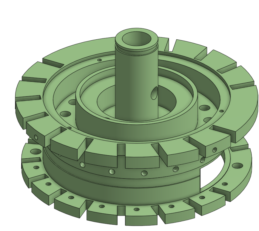
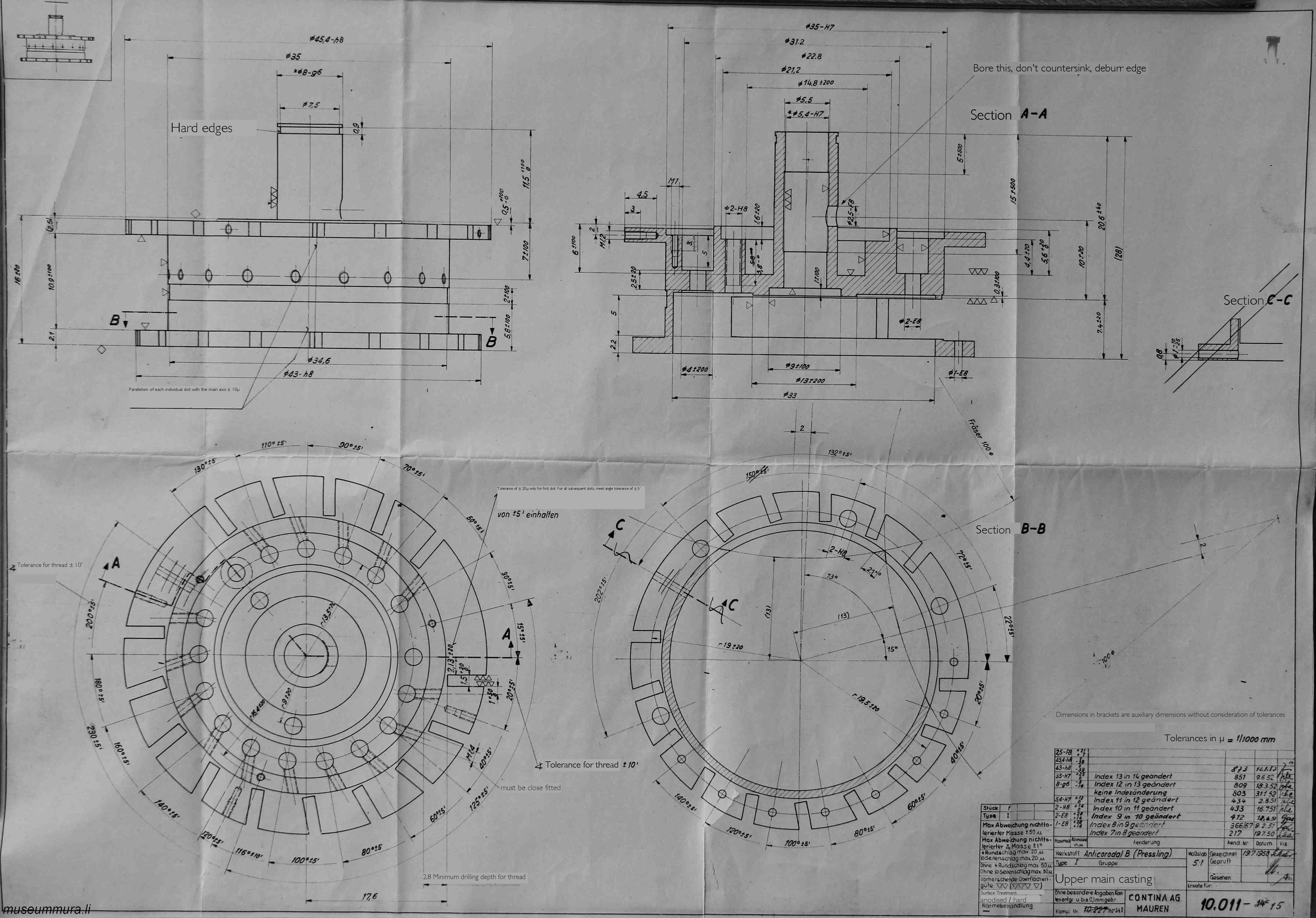
The upper main casting (10011) was by far the most difficult part to create. It could be due to the amout of operations or keeping track of the precise angles of each hole and milled pocket. This piece acts as the guide and resting point of many sub mechanisms in the overall design including the main shaft, carry mechanism, and counter mechanism.
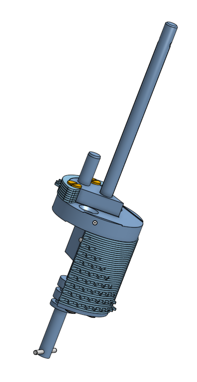
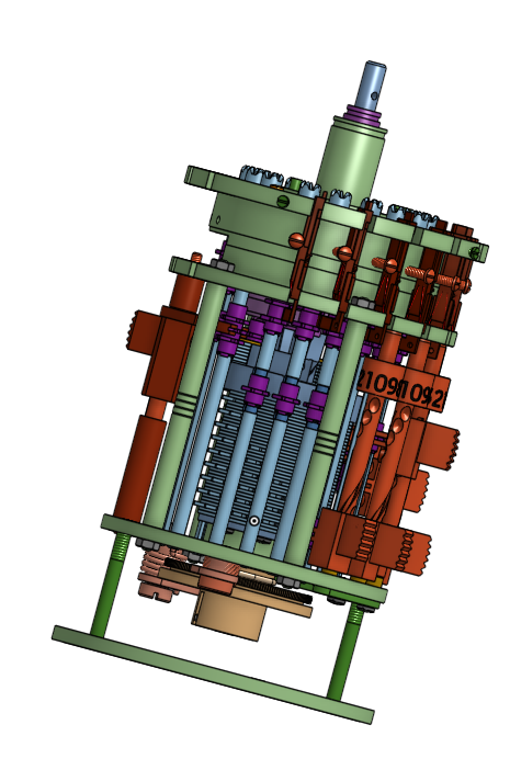
My favourite mechanism in this device is the stepped drum assembly and it's interaction with the counter mechanism.
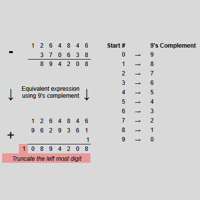
The stepped drum assembly can pull out to allow the calculator to enter "subtract mode". Subtraction is calculatde by using the 9's complement, similar to how a computer uses integer overflow to do subtraction through the 2's complement, but in base 10.
Aspirations
These devices hover around $2500 CAD so owning one for myself seems like a long shot, but I can yearn. I would love to make one but it is no easy feat as something like this would require the precision of making mechanisims akin to watch components.
If I were to make my own hand held mechanical calculator I would aim for a few modifications, the most notible being subtraction. the 9's complement subtraction is a really cool technique but it's drawback is that you have a hard time telling if a number is positive or negative. The output register may say 6452942 but that could be +6452942 or -3547057.
Thinking it through, The output registers will need a top and bottom spider gear that move up and down instead of the stepped drum. This will mesh with the either the top or bottom of the output gear, causing the necessary clockwise and anti-clockwise rotation needed for true subreaction. In addition to this, the carry mechanism will need to carry forwards and backwards. From there it should be easy enough to have a register that turns 90 degrees when the number dips below or rises above 0.